If you’ve ever stood in a prototype lab, watching a 3D printer spit out a plastic part layer by layer, you might have wondered: Are the high-performance CAD/CAM materials I supply for milling, grinding, and precision machining actually useful for rapid prototyping? For years, I heard this question time and again from prototype engineers and product designers who saw rapid prototyping (RP) as synonymous with entry-level thermoplastics or cheap photopolymers. As a CAD/CAM material supplier, that skepticism stuck with me—not because I doubted the value of traditional RP materials, but because I knew our materials could fill a gap no cheap filament or resin ever could. Today, I want to break down exactly how CAD/CAM materials work for rapid prototyping, where they outperform standard RP supplies, and why more product teams are ditching one-size-fits-all prototyping for materials built for precision, durability, and real-world performance. CAD/CAM Material

First, let’s get clear on what CAD/CAM materials actually are. Unlike standard RP materials, which are formulated exclusively for additive manufacturing (AM) processes like FDM, SLA, or SLS, CAD/CAM materials are engineered for subtractive manufacturing (SM): CNC milling, routing, and machining. Think high-density polyethylene (HDPE) for functional jigs, medical-grade polycarbonate (PC) for surgical prototypes, PEEK for aerospace components, and even high-temp thermoset composites for parts that need to hold up under extreme heat. For decades, CAD/CAM materials were locked in a separate lane from RP, seen as for production only, not for early-stage testing. That line started to blur about a decade ago, when product teams realized that a prototype printed in basic PLA might look like the final part, but it wouldn’t behave like it. PLA melts in a car’s dashboard, cracks under a bike’s pedal force, and can’t be autoclaved for medical device testing. CAD/CAM materials, on the other hand, replicate those performance characteristics almost exactly. That’s the core of why they work for RP: they don’t just look like the intended end product—they act like it.
Let’s talk about the biggest pain point in early prototyping today: speed to iteration. Product designers know that waiting two weeks for a 3D printed prototype that only works for a handful of tests is a waste of time. With CNC machining of solid CAD/CAM materials, you can get a functional part in 24 to 48 hours, same as most small-format FDM printers, but with none of the common RP material flaws. For example, when a team is testing a new consumer electronics casing, they might print three PLA prototypes to check fit, then realize they need a part that can survive being dropped, heated, and run through 10,000 assembly cycles. A CAD/CAM grade polycarbonate block can be milled in one day, sanded, and finished to match injection molding standards—no post-curing, no warping, no layer line gaps that cause structural weakness. That speed, paired with mechanical integrity, is what makes CAD/CAM materials a prototyping workhorse, not just a production material.
But let’s address the counterargument I still hear from designers: “Rapid prototyping is supposed to be fast and cheap, and CAD/CAM materials are more expensive than PLA or SLA resin.” It’s a fair point—upfront, a 4×8 inch block of PEEK costs more than a spool of PLA. But when you factor in rework, testing failures, and the cost of fixing parts that don’t perform as expected, CAD/CAM materials often save money in the long run. Let’s use a medical device example: a company developing a new orthopedic implant guide. They print a prototype in SLA resin for $50, then test it and find it cracks when pressed against bone. Another team mills the same design from CAD/CAM grade polyether ether ketone (PEEK) for $300, but that part passes 100% of load and sterilization tests on the first try. The first team has to reprint three more resin prototypes, each with tweaks, totaling $200 and two weeks of delay—time that could push back FDA approval. That’s the tradeoff: CAD/CAM materials cost more per part, but they reduce iteration cycles and de-risk the entire development process. For early-stage startups and Fortune 500 teams alike, that ROI is impossible to ignore.
Another area where CAD/CAM materials shine for rapid prototyping is part complexity and material consistency. Wait—didn’t I just say subtractive manufacturing is for solid blocks, not complex geometries? Modern CNC tools and 5-axis milling have changed that. You can mill parts with internal cavities, fine threads, and undercuts from a solid CAD/CAM block without the layering that plagues AM parts. For prototypes that need to mimic final part consistency—like gears that need to mesh smoothly, or fluid channels that can’t leak—CAD/CAM material milling produces parts with consistent, isotropic properties across the entire part. AM parts, by contrast, have anisotropic strength: they’re strong along the layer axis but weak across it, which means a SLA part might hold up for a fit test but fail when put under torque. I saw this firsthand last year with a robotics client testing a joint component. Their initial SLS prototype had a 30% strength gap between the vertical and horizontal axes, so when they ran torque tests, it snapped every time. They switched to a CAD/CAM grade aluminum 6061 block, milled it to the same geometry, and it passed all tests on the first run. That’s the kind of reliability that makes CAD/CAM materials ideal for prototyping functional, end-use-relevant parts.
Of course, CAD/CAM materials aren’t the right fit for every prototyping job. If you’re testing a disposable packaging concept or a decorative part that only needs to look right, a $20 FDM print is probably better. But for functional prototyping—when you need to test load, chemical resistance, heat tolerance, or mechanical performance—CAD/CAM materials outperform standard RP supplies every time. That’s why our company has seen a 40% year-over-year increase in CAD/CAM material orders specifically for prototyping, from industries ranging from automotive to medical to aerospace. We supply everything from affordable HDPE and ABS for general functional prototypes to ultra-high-performance materials like PEEK, ULTEM, and carbon fiber-reinforced thermoplastics for parts that need to withstand extreme conditions. The key, we’ve learned, is matching the right CAD/CAM material to the prototyping goal, not just grabbing the cheapest one.
Let’s get into a real-world example that’s close to home. Last quarter, we worked with a startup developing a portable lithium-ion battery pack for outdoor use. They were using SLA resin prototypes to test the casing, but the resin softened in temperatures over 120°F, cracked when dropped from 6 feet, and couldn’t be sealed properly for water resistance. They reached out to us, and we recommended a CAD/CAM grade high-heat ABS block. We milled two prototype casings in 48 hours—one for fit testing, one for environmental testing. The ABS prototype held up to 135°F, didn’t crack when dropped, and sealed correctly with a rubber gasket. The startup used that part to secure their first round of investor funding, and their production parts are being injection molded from the same ABS grade they tested in prototype. That’s exactly the value CAD/CAM materials bring to prototyping: they bridge the gap between early concept testing and final production.
One common misconception is that CAD/CAM materials are only for rigid parts. That’s not true either. We supply flexible CAD/CAM materials like Viton rubber and silicone-coated thermoplastics for prototyping gaskets, seals, and soft components. A client in the food and beverage industry was testing a new valve seal for a soda machine, and their initial SLS prototype was too stiff to create a tight seal. We suggested a millable silicone CAD/CAM block, which produced a flexible prototype that fit perfectly and passed 1 million cycle tests. Again, that’s a use case where CAD/CAM materials fill a gap standard RP can’t.
As a CAD/CAM material supplier, I’ll be the first to admit that additive manufacturing has transformed prototyping. But CAD/CAM materials haven’t become obsolete—they’ve evolved to meet the demand for parts that perform like the real thing. The future of prototyping isn’t choosing between AM and subtractive manufacturing; it’s using the right material and process for the job. For teams that need to de-risk their product before investing in production tooling, CAD/CAM materials are no longer a secondary option—they’re a core part of the prototyping toolkit.
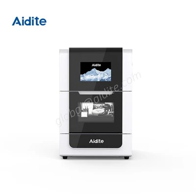
If you’re a product designer, engineer, or team lead working on a new prototype and want to learn how CAD/CAM materials can cut iteration cycles and improve part performance, we’d love to talk. Our team can help you select the right material for your testing needs, whether you need a small batch of prototypes for fit testing or high-performance parts for functional validation. Reach out to us to discuss your next prototyping project, and let’s build better parts—faster—together.
Glass Ceramic References
- Gibson, I., Rosen, D. W., & Stucker, B. (2015). Additive Manufacturing Technologies: 3D Printing, Rapid Prototyping, and Direct Digital Manufacturing. Springer.
- Kalpakjian, S., & Schmid, S. R. (2020). Manufacturing Processes for Engineering Materials. Pearson.
- ASTM International. (2019). Standard Guide for Functional Prototyping for Mechanical Systems (F2971-19). ASTM International.
- Dieter, G. E. (2000). Engineering Design: A Materials and Processing Approach. McGraw-Hill.
- Rapid Prototyping and Manufacturing Association (RPMA). (2022). Annual Report on Prototyping Material Adoption Trends. RPMA.
Aidite (Qinhuangdao) Technology Co., Ltd.
Aidite (Qinhuangdao) Technology Co., Ltd. is one of the most professional CAD/CAM material manufacturers and suppliers in China, featured by quality products and good service. Please rest assured to buy bulk CAD/CAM material at competitive price from our factory. Also, quotation is available.
Address: No.9 Dushan Road, Economic and Technological Development Zone, Qinhuangdao, Hebei Prov., China
E-mail: global@aidite.com
WebSite: https://www.aiditeglobal.com/
